| 110VDC INVERTER MEDIUM AND BIG SIZE |
The ELIT inverter, INV 110 series, are outcome of a long experience both in UPS and in converters field. All of our equipments distinguish
themselves by the employment of advanced technological components, excellent reliability and easy maintenance.
The simplicity of working is the main feature of all of our products.
These apparatus are studied to be employed in:
- Automation
- Petrochemical and industrial plants
- Telecommunication
- Railway field
- Civil and military aviation
- Civil and military nautical
|
|
PRINCIPLES OF WORKING
The IGBT ELIT inverter, INV 110 series, transforms the continuous voltage into an alternating sinusoidal stabilized voltage.
The PWM modulation technique used reduces the harmonic content of the output and limits voltage deviations under step load conditions.
FEATURES
The main components that composed the inverter ELIT INV 110 are:
. Input filter
. IGBT conversion unit (Inverter)
. Output filter
. Output insulation transformer
. Static switch as option
. Manual by-pass as option
. Insulation transformer for emergency line as option
. Parallel kit feature as option
INVERTER ELIT INV 110 COMPOSITION
| a) |
|
IGBT Greatz bridge type with PWM regulation |
| b) |
|
Output current limitation |
| c) |
|
Output voltage detector min - max |
| d) |
|
Heat sink temperature detector |
| e) |
|
DC link voltage detector min - max |
| f) |
|
Short circuit running |
STATIC BYPASS SWITCH (AS OPTION)
The bypass static commutator transfers the load from the inverter to mains upon failure or overload
The transfer occurs automatically without break.
Characteristics
| a) |
|
Min - max mains voltage monitor |
| b) |
|
Quartz mains frequency monitor |
| c) |
|
Mains - inverter transfer manual or automatic and vice versa |
| d) |
|
Transfer inhibition mains - inverter after 5-6 attempts |
| e) |
|
Heat sink temperature detector |
If any condition out of inverter characteristics occurs, the static bypass switches the load to the
emergency line and the inverter is disconnected. When the normal conditions are restored, the inverter will be connected
|
|
|
|
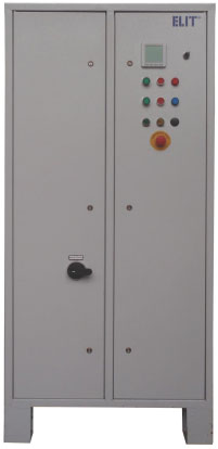
CONTROL PANEL
The control panel is divided in three parts:
- LCD display (PMD)
- LED indicators
- Keyboard
INTERFACES
The apparatus are provided with a dry to remote the following signaling:
- inverter alarm
- inverter running
- ON/OFF remote control as option
Additional interface modules for measurements transmission as option:
- RS485 interface
- RS232interface
- Profibus interface
- Lonworks interface
- Output pulses
- Analogical output
- Alarms
MONITORING CONTROL SYSTEM
(as option)
The Monitoring Control System manages communication from and to remote devices, distributed in two ways:
. Physical connections
. Wireless connections
These two kinds of connections can be combined at any way, to use in the better way the available infrastructures for the
pplication (telephone cable, ADSL/HDSL connections, optic fiber cable, GSM/GPRS modem, UMTS modem, HSPDA modem).
The System can use dedicated lines by cable, optic fiber or it can use a point of access through LAN network or internet in
remote plant allowing the management with automatic calling or through request of the control device.
|
|
The Workstation logs on Central System through LAN or Internet network allowing the complete compatibility of the System.
The Monitoring Control System has a Client platform, designed for mobile phones, with Java platform. It allows to access
directly with the phone to all data of the Server and to perform all maintenance actions in remote.
The Central System controls every access with login procedure, classifying them in different levels according
the operative level that you desire to give at each user.
CUSTOM VERSION
We realize custom apparatus according to customer's technical data employing the standard series sets
and therefore with experimented feature.
Fix or variable input voltage
Fix or variable output voltage
Cabinet protection degree for outdoor use
Extended working temperature from -40°C to 50°C
Parallel configuration kit
Parallel cabinet with system switches
Voltage accuracy calibration with potentiometer
Frequency accuracy calibration with potentiometer
Distribution cabinet
Drop line compensator
Mobile version
Under bridge configuration
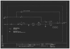
BLOCK DIAGRAM
|
|
|
| Model |
INV110
5 |
INV110
10 |
INV110
15 |
INV110
20 |
INV110
25 |
INV110
30 |
INV110
45 |
INV110
60 |
| Rated power kVA/kW |
5/4 |
10/8 |
15/12 |
20/16 |
25/20 |
30/24 |
45/36 |
60/48 |
| |
|
|
|
|
|
|
|
|
| INPUT |
|
| Nominal voltage |
110Vdc |
| Voltage tolerance |
88 ÷ 132Vdc |
| Emergency line as option |
400V 3Ph or 230V 1Ph, 50/60Hz
(120, 208, 230, 440, 480 and 575V as option) |
| |
|
|
|
|
|
|
|
|
| OUTPUT |
|
| Voltage |
400V 3Ph+N or 230V 1Ph
(120, 208, 230, 440, 480 and 575V as option) |
| Frequency |
50 o 60Hz ± 0.1% |
| Static stability |
±1% |
| Dynamic stability |
±8% |
| Crest factor |
1.414 ±3% |
| Working |
Continuously |
| Waveform |
Sinusoidal |
| Overload |
125% for 10 minutes, 150% for 1 minute |
| Transfer time |
20 msec. |
| THD distortion |
< 3% |
| Efficiency |
> 90% |
| |
|
|
|
|
|
|
|
|
| MISCELLANEOUS |
|
| Operating temperature |
-25 ÷ +50°C |
| Relative humidity |
0 from 95% without condensing |
| Altitude |
1000m without derating |
| Protection degree |
IP20 (IP31, IP41 and IP54 on request)) |
| Cooling |
Forced air (natural as option) |
| Dimensions (mm) |
400x600x1200 |
600x800x1200 |
800x600x1500 |
| Weight (kgs) |
100 |
120 |
130 |
150 |
220 |
270 |
320 |
450 |
| |
|
|
|
|
|
|
|
|
| STANDARDS |
|
| Safety |
IEC/EN 62040-1-1, IEC/EN 60950-1 |
| EMC |
IEC/EN 62040-2, IEC/EN61000-3-2, IEC/EN61000-6-2 |
| Performance |
EN 62040-3 |
| |
|
|
|
|
|
|
|
|
|
|
|
| Model |
INV110
80 |
INV110
100 |
INV110
120 |
INV110
160 |
INV110
180 |
INV110
200 |
INV110
250 |
INV110
300 |
| Rated power kVA/kW |
80/64 |
100/80 |
120/96 |
160/120 |
180/144 |
200/160 |
250/200 |
300/240 |
| |
|
|
|
|
|
|
|
|
| INPUT |
|
| Nominal voltage |
110Vdc |
| Voltage tolerance |
88 ÷ 132Vdc |
| Emergency line as option |
400V 3Ph or 230V 1Ph, 50/60Hz
(120, 208, 230, 440, 480 and 575V as option) |
| |
|
|
|
|
|
|
|
|
| OUTPUT |
|
| Voltage |
400V 3Ph+N or 230V 1Ph
(120, 208, 230, 440, 480 and 575V as option) |
| Frequency |
50 o 60Hz ± 0.1% |
| Static stability |
±1% |
| Dynamic stability |
±8% |
| Crest factor |
1.414 ±3% |
| Working |
Continuously |
| Waveform |
Sinusoidal |
| Overload |
125% for 10 minutes, 150% for 1 minute |
| Transfer time |
20 msec. |
| THD distortion |
< 3% |
| Efficiency |
> 90% |
| |
|
|
|
|
|
|
|
|
| MISCELLANEOUS |
|
| Operating temperature |
-25 ÷ +50°C |
| Relative humidity |
0 from 95% without condensing |
| Altitude |
1000m without derating |
| Protection degree |
IP20 (IP31, IP41 and IP54 on request)) |
| Cooling |
Forced air (natural as option) |
| Dimensions (mm) |
800x800x1800 |
1300x1000x1800 |
1500x1000x1800 |
| Weight (kgs) |
600 |
750 |
900 |
1100 |
1300 |
1400 |
1800 |
2000 |
| |
|
|
|
|
|
|
|
|
| STANDARDS |
|
| Safety |
IEC/EN 62040-1-1, IEC/EN 60950-1 |
| EMC |
IEC/EN 62040-2, IEC/EN61000-3-2, IEC/EN61000-6-2 |
| Performance |
EN 62040-3 |
| |
|
|
|
|
|
|
|
|
|
|
ELIT Srl reserves his right to do modifications to his
products without notice |
| download the pdf |
 |
ask for a quotation |
 |
|
|

 The company
 Products
 Support
 Contact
 Quality Plan
 Italiano